Categories:
News
Research
Industrial Automation
Automation Components
Electric Components
Robots
Artifint
New Wave
Motors
Practical
News
Research
Industrial Automation
Automation Components
Electric Components
Robots
Artifint
New Wave
Motors
Practical
Tags:
announcement, website, testing, PLC rack, I/O, Cable, Parallel communication, Serial communication, ASCII, RS232, RS-232 Communication, ProfiBus, Industrial robots, manipulator, Cartesian robot, SCARA Robot, Articulated robot, end-of-arm-tooling, Robotics, Metalcasting, automotive industry, Integrated force sensing, shunt, electric current, Human - Machine Interface, HMI, MMI, Human Factors Engineering, Usability Engineering, User Interface, Systems Engineering, Opton, T-WIN20, T-WIN20 KDM, robot bender, pipes, PROFIBUS, Process Field Bus, communication, automation technology, PROFINET, Industrial Ethernet, Central Association for the Electrical Industry, ZVEI, PROFIBUS FMS, PROFIBUS DP, PROFIBUS International, field-bus, OSI Network model, Field bus Data Link, FDL, RS485, fiber-optic transmission, Manchester Bus Power, MBP, bus topology, Fieldbus Message Specification, Decentralized Periphery, PROFIBUS PA, PROFIdrive, PROFIsafe, The PROFIBUS User Organization, Contactor, Relay, Differences, automation, switch, power contacts, auxiliary contacts, contact springs, electromagnet, coil, armature, Grounding, shielding, EMI, Shields, PWM, RF signal, Magnetic coupling, Pulse-width-modulation, PWM simulation, EMI noise, CE mark, and many more...
Grounding and shielding
 Grounding and shielding is many times referred to as being almost mystic, but effective grounding and shields work on solid engineering principles. There are four paths that let undesired signals get into a system: magnetic or inductive coupling, capacitive coupling from high-speed voltage changes (dV/dt), direct coupling, and radiated, or RF, coupling. One may not be able to predict the exact path a noise signal takes, just as one cannot predict the exact path of lightning. But one knows how to limit the chances of getting struck. Lightning is nothing more than one of the most powerful EMI events. Manufacturers typically provide connection recommendations on how to minimize EMI and other electrical noise issues on their products.
In EMI terms, there is the receiver (referred to as the victim), and the source of the signals. Sometimes the victim of an EMI problem is also the source of the problem. It may be difficult trying to determine the source of the noise in circuits that contain feedback loops, as do most motor-speed controls and power supplies. In the case of power supplies or servo amplifiers, tracking down noise sources can be a daunting task. Current and voltage feedback in these types of devices use relatively high-gain stages that can easily feed back upon themselves. Care must be taken to preserve the integrity of the intended signal with robust rejection of undesired signals.
Many switch-mode power supplies contain both current and voltage feedback. Often, they operate at higher frequencies (typically 400 kHz and up) that can create capacitive, magnetic (inductive), and RF-type interference problems. Inadequate shielding, or a poor layout of the voltage sense line, may let interference from the pulse-width-modulated (PWM) output interfere with proper sensing. The power supply becomes both the source and victim of the problem. The only solution here is to isolate the signals with layout and shielding changes. Shield the noise source with a 360° coverage braided cable. The PWM edges can also be substantially tamed with either common or differential-mode inductors, depending on the cause. The inductors slow the rise and fall times of the wave, reducing dV/dt and dI/dt effects. The slower rise time also reduces the harmonic frequencies. This in turn may break the coupling since the receiving antenna may not be able to receive the lower frequency.
Shields
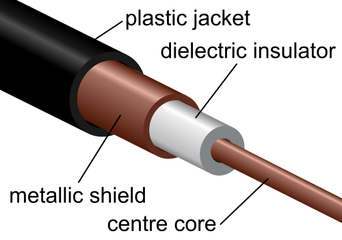
Shields merely act as an isolation barrier to a signal. Using one barrier on the source of the noise and one barrier on the receiver typically delivers the greatest integrity. Shields may be necessary, but, ideally, there should be no signal to shield against. It is important to understand what is causing the noise and whether it can be resolved. There are many techniques relating to noise that truly resolve the source of the problem, not just reduce noise levels. For example, the high dV/dt signals seen in pulse-width-modulations may be impacted by slowing the rise time. The change in dV/dt may break any capacitance-coupling factor should the rise time fall below the reactance level.
RF signals
Unfortunately, it is fairly easy to create RF signals. For example, an electric arc jumping across a spark gap generates a wide range of frequencies. Relays are common culprits, as contact arcing may arise when the relay opens. The subsequent electromagnetic field generated by the spark may cause major interference problems within the equipment. In addition, the EMI noise is broadcast where its reception may interfere with proper operation of other nearby equipment.
An understanding of the transmission and reception mechanism of a radiated signal makes it possible to devise techniques that effectively eliminate their associated problems. First, it takes an antenna to transmit or receive a radiated signal, but any type of conducting surface can function as an antenna. There are two fields present on any working antenna: an E-field that represents voltage and an H-field, which is magnetic. When they are in phase on the antenna, they will support each other and maintain their resonant relationship. This is sometimes referred to as sympathetic oscillation. The area within one half wavelength (1/2 λ) of the source is called the near field or inductive area. The RF signal within the near field shows a 90° shift between the E-field and the H-field, making a true analysis (called characterization) of the signal unreliable due to cancellations and intermodulation. However, the magnetic field is the primary affecter; thus, a magnetic shield is more effective to block the transmission source and prevent reception.
Beyond 1/2 λ, in the far or radiative field area, the electric field has the predominant effect. The magnetic and voltage fields, E and H, respectively, or orthogonal are 90° apart and are sympathetic or supportive of one another. Characteristics of the signal are plainly visible. For example, electromagnetic compatibility (EMC) labs measure signals 30 MHz and higher at distances over 10 m from the unit under test (UUT). Ten meters is the 1-λ wavelength for 30 MHz. Typically, they use an E-field (voltage) antenna as a receiver.
Magnetic coupling
Pulse-width-modulation signals from servoamplifiers and power supplies are often noise culprits, projecting their signals into unwanted areas. These unwanted signals have sufficient power to, in some cases, actually turn on nearby devices. For example, a high-magnetic field across a device may illuminate LEDs within the field. At the same time, any solid-state device connected to the same circuit may partially conduct at the wrong time. An egregious example is the PWM output from servodrive systems. Typically, these outputs are sent via long cables to motors that effectively represent an inductive load in electrical terms. The combined effect of these factors generates a perfect storm for careless cable selection, grounding, shielding, and connections. Fortunately, answers do exist to control this well-known combination of problems. The complex model of a motor amplifier, cable, and motor includes elements of inductance, resistance, capacitance, and current, along with back-EMF voltages. This complex reactive load may not function as one thinks, but it is possible to use it to resolve the interference issues. In a majority of cases, this type of system is prone to the H-field or magnetic effect of the PWM signals. Interference is typically eliminated by surrounding this cable with a magnetic shield grounded at both the amplifier and motor terminals.
When a ground is not a ground
One of the most common direct-coupled noise sources arises when the ground used for reference or return is not referenced to earth as expected. This is especially prevalent in sensitive high-gain circuits. An example is a power system where a neutral line serves as the ground reference. Earth or safety ground and the neutral wire connect to the same potential in the power box. The difference is that neutral is a current-carrying conductor while an earth ground should never carry current under normal circumstances. If the signal was monitored at this point, you would most likely see voltage fluctuations using the neutral line as reference, but you would not on the ground connection. If the power return line of the equipment were inadvertently connected to ground instead of neutral, it most likely would operate. But besides creating an electrical danger, it would likely put unintended noise on the ground line, negatively affecting all of the devices connected to that ground. While the proper answer to this problem is to connect the system correctly, the power line inputs of the equipment should also contain filters that block sensitive devices from power-line disturbances. These power-line disturbances are quite common and filters from a number of different manufacturers sufficiently address this issue.
PWM simulation
The complex conditions for EMI noise are related, but not limited, to motor inductance, motor resistance, cable capacitance, shielding, and the capacitive effects of the motor windings. Add to this the unpredictable nature of what the PWM will do with back-EMF voltages, and the possibilities become numerous. A model of the PWM technique can be illustrated by way of an electronic simulation program. To start, the motor's complex electrical qualities are modeled as an inductor in series with the resistance of the motor. Motor capacitance is lumped in with the cables, while one-third of the PWM bridge drive is modeled using IGBTs to simulate a single phase of the drive. The standard simulation produces an indication of ringing on the leading edge of the PWM output. It happens at a substantially higher frequency than that of the PWM waveform and is usually only on the rising edge of the pulse. Given this propensity to oscillate, and the fact that each transistor will produce ringing, it is easy to see how the frequencies involved can couple into a load that contains uneven RLC (resistive, inductive, capacitance) characteristics. Common-mode noise, as well as voltage spikes from the di/dt through the inductance of the motor winding, can damage insulation, producing an electrical failure in the motor or drive. These oscillations are prevalent on the PWM of all transistors in the output power bridge. Any load imbalance results in current flow from the oscillation source to ground via this RLC circuit. If the inductance path to ground is a lower impedance, it usually results in some of those leading-edge oscillations leaking onto the signal returns.
To correct this problem requires a threefold attack. First, reduce the emissions. Second, shield the receiver to break the coupling. And third, force a current path to ground via the intended connections. One drive model places an inductor in series to slow the rise time of the PWM signal and reduce oscillations. Analysis of the PWM signal shows there is some improvement, but not enough to consider this an effective answer. While they are easier to shield than the original oscillations, there are still some significant oscillations that could couple into the system. Reducing the amplitude and frequency of these oscillations further should be the goal here. An alternative solution is to add a snubbing circuit. This often results in a well-controlled PWM pulse without the wild oscillating rising edge that can lead to EMI noise. This model includes both a common-mode inductor as well as a series mode matched to cable capacitance. The oscillation of this PWM edge is benign. The drawback of this design, however, is that it slows PWM power changes in the drive. Now with a good connection to ground and a lower frequency of ringing, it is significantly easier to eliminate the noise. A straightforward shield and ground are likely adequate to minimize the EMI infiltration without significantly adding to the cost of the system. Do not forget that cables also contribute to the effect. They are part of the circuit. The combination of cable capacitance and motor inductance can produce a "tank circuit" that resonates at a frequency related to the rise time of the PWM. Should this happen, even accidentally, there may be catastrophic results. As can be seen from the final model, both transmission and reception of EMI can be taken care of with shields, inductance, and capacitance in the right areas. This is the best answer for an existing design, with minimal impact on delivering a sound product.
Manufacturers that are CE compliant should have an intimate understanding of EMI and EMC compliance. Drives displaying the CE mark should come with information about how to maintain compatibility, as well as how to supply external products for special cases.
About the author
Lee Stephens is a senior motion control engineer at Kollmorgen, with more than 20 years of motion control engineering experience, including mechatronic design engineering for systems in use in electronic manufacturing, textile, glass manufacturing, and printing industries. For more information, contact support@kollmorgen.com.
This article can be found also on http://www.isa.org
This post belongs to category: